
Challenges of Multi-band Antenna Radomes
- Difficulty in ensuring RF transparency across all frequency bands
- Even when RF transparency is ensured, it is difficult to widen the radiation angle

Smart Cellular Board (SCB), a low dielectric foam material, solves these issues and enables radomes for multi-band antennas with excellent RF transparency.
Key Points of This Article
- Multi-band and satellite communication antennas require radome designs that can support multiple frequency bands while maintaining stable RF performance.
- The RF transparency of a radome is strongly influenced by the material’s dielectric constant (Dk) and dissipation factor (Df).
- Furukawa Electric’s low-dielectric foam material, Smart Cellular Board (SCB), helps reduce transmission loss caused by variations in frequency and signal incidence angle.
- With a dielectric constant below 2.0—a level that is difficult to achieve with solid resin materials—SCB is well suited for radomes used in high-frequency communication antennas.
What is a Multi-band Antenna?
A multi-band antenna is an antenna capable of supporting multiple frequency bands. By integrating multiple frequency bands into a single device, it enables system miniaturization and multifunctionality. For applications handling multiple frequency bands, such as mobile communication base stations, it is an essential technology.
In recent years, satellite communications such as Starlink have gained attention as part of NTN (Non-Terrestrial Network) to expand communication coverage and support emergency communication networks. Multi-band antennas are also being studied in this field.
In satellite communications, within a single frequency band, there are effectively two types of frequency usage:
- Uplink (from ground to satellite):
Higher frequency is used to ensure communication capacity, while attenuation is compensated by transmission power - Downlink (from satellite to ground):
Lower frequency is used to reduce attenuation due to limited power availability
Multi-band antennas are equipped with radomes (antenna covers) to protect internal components. Radomes (antenna covers) must function as protective enclosures while also ensuring high RF transparency for each frequency band.
Challenges and Requirements for Multi-band Antennas
Ensuring RF transparency across multiple frequency bands
As described above, radomes(antenna covers) must allow radio waves in multiple frequency bands to pass efficiently. When radio waves enter a radome(antenna cover), they are divided into reflection, absorption and transmission. To increase transmission, reflection and absorption must be minimized.
To reduce the reflected component of radio waves, it is important to minimize the difference in dielectric constant between air and the radome material, thereby matching their characteristic impedance (note).
In other words, the closer the dielectric constant (Dk) of the radome material is to 1, the more effectively reflection can be suppressed.
Additionally, to reduce absorption, a lower dissipation factor (Df) is required
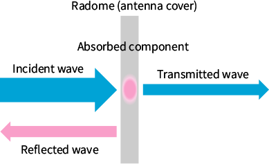
However, radomes(antenna covers) used in conventional wireless communication antennas, solid resin materials such as polycarbonate (PC) and acrylonitrile butadiene styrene (ABS) are commonly used. Because these materials have relatively high dielectric constants (εr,Dk), reflection occurs at the interface between air and the radome material, resulting in reduced RF transparency.
As a countermeasure, the radome(antenna cover) thickness is often optimized based on wavelength to cancel reflected waves.
As a countermeasure, the thickness of the radome (antenna cover) is adjusted to a value that accounts for the wavelength of the radio waves in use. By superimposing and canceling the two reflected waves generated at the front and back surfaces of the radome material, the apparent reflection component is reduced, thereby ensuring high RF transparency.
The figure below is a schematic diagram illustrating this process.
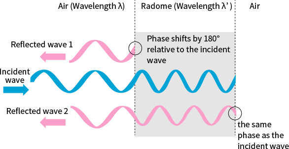
a) When reflected waves 1 and 2 are 180° out of phase (opposite phase)

b) When reflected waves 1 and 2 are in phase

When a radio wave enters the radome(antenna cover) from air, reflection occurs at both the front and rear surfaces. In the case of reflection wave 1, which is generated when waves enter the radome material from air, the phase of the reflected wave is shifted by 180° relative to the incident wave because the waves enter from a region of lower relative permittivity (εr, Dk) to a region of higher relative permittivity.
On the other hand, for reflection wave 2, which is generated when the wave is incident from the radome material into the air, the wave enters from a region of higher relative permittivity (εr, Dk) to a region of lower relative permittivity. Therefore, the phase of the reflected wave is the same as that of the incident wave.
Furthermore, the wavelength of an electromagnetic wave propagating within the radome material is shortened due to the influence of the dielectric constant (εr, Dk). Compared to the wavelength in air (λ), it changes to the wavelength in the dielectric medium (λ′), as expressed in Equation (1).
- λ’: Wavelength of the electromagnetic wave in the dielectric medium
- λ: Wavelength of the electromagnetic wave in air
- εr: Dielectric constant (Dk)
In theory, when the thickness of the radome material (t) satisfies Equation (2), reflected waves 1 and 2 cancel each other through superposition. As a result, no apparent reflection occurs, and RF transparency is improved.
- t: Radome(antenna cover) thickness
- n: Integer
Conversely, when the thickness of the radome material (t) satisfies Equation (3), reflected waves 1 and 2 reinforce each other through superposition. This increases the apparent reflected component, leading to a reduction in RF transparency.
However, in the case of multi-band antenna radomes, if RF transparency is ensured using the method based on Equation (2), it is necessary for each frequency to satisfy Equation (2). As a result, it becomes difficult to ensure good RF transparency for all frequencies with a single radome thickness (see figure below).
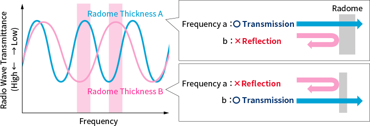
To solve this issue, instead of relying on Equation (2) to improve RF transparency, it is essential to reduce the dielectric constant (Dk) of the radome material and suppress the reflection of radio waves at the interface between air and the radome.
-
(note)
Characteristic impedance:
Characteristic impedance is the ratio of the electric field to the magnetic field when an electromagnetic wave propagates through a medium. The smaller the difference in characteristic impedance between two materials, the less likely reflection occurs at their interface.
Reduction in RF transparency due to Incident Angle Changes
In multi-band antennas with beam steering, such as mobile communication base stations and satellite communications, radio waves must be transmitted and received at various angles. When RF transparency is ensured using Equation (2), changes in the transmission angle result in changes in the effective thickness of the radome. As a result, RF transparency varies depending on the angle (see figure below).
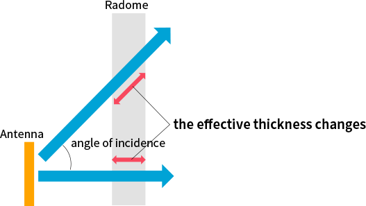
To address this issue, complex adjustments are required, such as modifying the radome shape to adjust the angle of incidence and locally adjusting the thickness of the radome. To solve this issue, it is necessary to reduce dielectric constant (Dk) and suppress reflection itself, rather than relying on Equation (2) to improve RF transparency.
Benefits of Using Smart Cellular Board
Ensuring RF transparency across All Frequency Bands
Smart Cellular Board (SCB) utilizes Furukawa Electric’s proprietary foaming technology to enable the foaming of heat-resistant resins such as engineering plastics and super engineering plastics, which have traditionally been difficult to foam.
The figure shows a dielectric map comparing solid plastic materials and Smart Cellular Board (SCB). Through foaming, SCB introduces air into the base resin, making it possible to reduce both the dielectric constant (Dk) and the dissipation factor (Df) of the material by bringing them closer to those of air.
In particular, SCB achieves a dielectric constant (Dk) of less than 2.0, which is difficult to obtain with solid plastics.
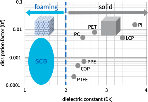
As a result, when SCB is used as a radome, reflection at the interface between air and the radome is reduced, enabling excellent RF transparency without relying on thickness design based on Equation (2).
In addition, SCB has a closed-cell structure, preventing water ingress into the cells and suppressing degradation in RF transparency due to moisture absorption, which is a concern in conventional foamed materials. This enables stable RF transparency across the entire bandwidth of each frequency, even in multi-band antenna applications handling multiple signals.
Ensuring RF transparency Across a Wide Range of Incident Angles
SCB achieves dielectric constant below 2.0, which is difficult with solid materials.
As a result, when SCB is used as a radome, reflection of radio waves at the interface between air and the radome is suppressed, enabling excellent RF transparency without relying on Equation (2). Consequently, even when radio waves are transmitted and received at various angles from the antenna (i.e., when the effective thickness of the radome changes), stable RF transparency can be ensured over a wide angular range.
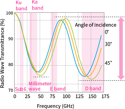
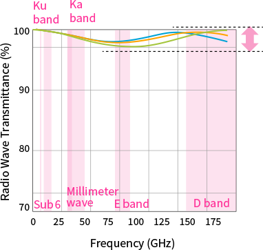
Simulation of RF transparency for PET sheet (solid) and SCB-PET
FAQ
-
A
A multi-band antenna is an antenna that can support multiple frequency bands. By integrating multiple frequency bands into a single device, it contributes to system miniaturization and enables multifunctional equipment.
-
A
Radome design for multi-band antennas is difficult because the optimal thickness conditions differ for each frequency, and the effective thickness changes depending on the angle of incidence, requiring complex structural design for proper adjustment.
-
A
Furukawa Electric’s Smart Cellular Board (SCB) reduces impedance mismatch with air through its low dielectric constant (Dk) and low dissipation factor(Df), suppressing reflection and absorption, and enabling stable RF transparency across a wide bandwidth without complex structural design.
“Smart Cellular Board” and “SCB” are registered Japanese trademarks of Furukawa Electric Co., Ltd.
Our SCB can solve the issues often faced when designing base stations that use high frequency radio waves in 5G/ Beyond 5G/ 6G telecommunications.